FGTECH Galletto (0475 pre-patched) + v53/v54 HEX & EPT Repair Pack

FGTECH Galletto Pre-patched - Wiring Diagrams Manual 0475

FGTECH Galletto (0475 pre-patched) + v53/v54 HEX & EPT Repair Pack
FGTECH Galletto Pre-patched - Wiring Diagrams Manual 0475

Post #41

its flashing red light and then click and then it says cannot communicate with device
 

Post #42

its flashing red light and then click and then it says cannot communicate with device

The "Click" you heard is the most important clue!

If you hear a CLICK from the relays, you are NOT in Boot Mode.

The "Click" means the chip started up normally, turned on the relays, and is ignoring your computer. This confirms that Pin 57 was not grounded correctly at the exact moment you plugged it in.

Here is the hard truth: You have two problems happening at the same time.

Problem 1: The Software (LPC2104 is WRONG)
You said earlier: *"i cant select LPC2119... its only LPC2104"*
You cannot proceed with LPC2104 selected. It is a different language. The chip will never answer.

If your Philips Utility is stuck on LPC2104, STOP using it. It is useless for this board.

Download "Flash Magic" (It is free).
1. Install Flash Magic.
2. Select Device: LPC2119 (It will be in the list).
3. COM Port: Your USB Port.
4. Baud Rate: 9600.
5. Interface: None (ISP).
6. Oscillator: 16.000.

Problem 2: The "Click" (Missed Boot Mode)
You are missing Pin 57. Since counting is hard, use the "Broad Sweep" method.

Do not try to touch just one leg.
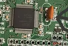
1. Find the Orange Crystal.
2. Look at the black chip legs directly BELOW the crystal (away from the corner).
3. Take your ground wire (connected to the USB metal shell).
4. Lay the wire across 3 or 4 legs in that area below the crystal.
* *It is safe to short Pin 57, 56, and 55 to ground all at once.*
* *Just stay away from the top corner (Pin 64).*
5. PRESS DOWN FIRMLY.
6. Plug in the USB cable.
7. LISTEN.
* If you hear a CLICK: You failed. Unplug and try again. Move the wire slightly.
* If it is SILENT: You are in Boot Mode! Success!

Only when it is SILENT:
1. Keep holding the wire for 2 more seconds.
2. Release the wire.
3. Click "Start" in Flash Magic (or Read Device ID).

Summary:
1. Get Flash Magic (because your Philips software is set to the wrong chip).
2. Short the group of pins below the crystal to Ground.
3. Plug in.
4. NO CLICK = GOOD.
5. CLICK = BAD (Try again).
 

Post #44

now its not click but i have same message again

NO CLICK = SUCCESS!
You have done the hard part. The chip is now in "Boot Mode" and waiting for commands.

The reason you still get "Cannot Communicate" is because your software is trying to talk to an LPC2104, but your chip is an LPC2119. They speak different languages.

You cannot use the software if it is stuck on LPC2104. It will fail 100% of the time.

Solution: Use Flash Magic (Free)

Since your Philips software is broken/locked, download Flash Magic. It is the standard tool for these chips.

Exact Settings for Flash Magic:
  • Section 1 - Communications:
    • Device: LPC2119 (You must select this!)
    • COM Port: The one from your Device Manager (e.g., COM3).
    • Baud Rate: 9600 (Do not go higher).
    • Interface: None (ISP).
    • Oscillator (MHz): 16.000
  • Section 2 - Erase:
    • Check "Erase blocks used by Hex File".
  • Section 3 - Hex File:
    • Browse and select your firmware file (the fix file).
  • Section 4 - Options:
    • Check "Verify after programming".

The Procedure (Do this exactly):
1. Close all other software.
2. Unplug USB.
3. Hold your wire on the pins below the crystal (Ground).
4. Plug in USB.
5. LISTEN: No Click? Good.
6. Count to 3.
7. Release the wire.
8. Click Start in Flash Magic.

If it still fails:
Go to Device Manager -> Ports -> USB Serial Port -> Properties -> Port Settings -> Advanced.
Make sure Latency Timer is 1.
Make sure the COM Port number is low (between COM1 and COM4). If it is COM20 or higher, change it to COM1 or COM2.
 

Post #46

i have that 2119 now but same thing

Okay, good. You have the right chip selected (LPC2119) and you are getting NO CLICK (Boot Mode). This is huge progress.

The only remaining variable is the Baud Rate or the Crystal Frequency.

Since you are in Boot Mode (No Click), the chip is listening. But it is listening at a specific speed. If your software sends data at the wrong speed, the chip ignores it.

Try these combinations in order:

Attempt 1:
  • Device: LPC2119
  • XTAL: 16000 (This is what is printed on your crystal)
  • Baud Rate: 9600
  • Action: Unplug -> Hold Wire (Ground pins below crystal) -> Plug In -> Wait 3s -> Release -> Read Device ID.

Attempt 2:
  • Device: LPC2119
  • XTAL: 12000 (Sometimes the software expects this even if the crystal says 16000)
  • Baud Rate: 9600
  • Action: Unplug -> Hold Wire -> Plug In -> Wait 3s -> Release -> Read Device ID.

Attempt 3:
  • Device: LPC2119
  • XTAL: 16000
  • Baud Rate: 19200 (Sometimes 9600 is too slow for some USB adapters)
  • Action: Unplug -> Hold Wire -> Plug In -> Wait 3s -> Release -> Read Device ID.

Attempt 4:
  • Device: LPC2119
  • XTAL: 12000
  • Baud Rate: 19200
  • Action: Unplug -> Hold Wire -> Plug In -> Wait 3s -> Release -> Read Device ID.

One of these 4 combinations WILL work.

Important Check:
Go to Device Manager -> Ports (COM & LPT).
Does it say "USB Serial Port (COMx)"?
Or does it say "USB Serial Converter"?
It MUST say "USB Serial Port". If it doesn't, you need to install the VCP (Virtual COM Port) driver from FTDI.

Final Trick:
If you are using a laptop, plug the USB cable directly into the laptop. Do not use a USB Hub or extension cable. These often cause timing issues with FTDI chips.
 

Post #47

nothing works

You are very close. The fact that you have NO CLICK means you have successfully forced the chip into Boot Mode. The chip is awake and listening!

The problem now is that the chip and the computer are "speaking backwards" to each other.

This happens often if you used MProg or a "Fix" file on the FTDI chip. It resets the internal settings to default, but many Galletto boards require the signals to be Inverted.

The Final Fix: FT_Prog (Invert Signals)

You need to check if your cable needs "Inverted" signals.

1. Download FT_Prog (it is a free tool from FTDI, similar to MProg but newer).
2. Plug in your USB cable (you don't need the wire bridge for this part).
3. Open FT_Prog.
4. Click Devices -> Scan and Parse.
5. Your device should appear in the list.
6. Expand the tree: Hardware Specific -> Invert RS232 Signals.

Look at the checkboxes:
  • Invert TXD
  • Invert RXD

If they are unchecked:
1. Check (Tick) both Invert TXD and Invert RXD.
2. Click the Program Devices icon (lightning bolt) in the toolbar.
3. Click Program.
4. Once finished, unplug the USB cable and plug it back in.

Now try the Boot Mode procedure again:
1. Hold Wire (Ground to pins below crystal).
2. Plug in USB.
3. NO CLICK (Silence).
4. Release Wire.
5. Try Flash Magic (LPC2119, 16000, 9600).

***

If they were ALREADY checked:
1. Uncheck them.
2. Program.
3. Unplug/Replug.
4. Try Boot Mode again.

*Explanation: The Red Light flashing means data is leaving your computer. The "Cannot Communicate" means the chip isn't answering. Usually, this is because the 1s and 0s are flipped (Inverted). Toggling this setting fixes 99% of "No Click but No Comms" cases.*
 

Post #48

is that black thing right
 

Attachments

  • 70e487a3-2f0b-4310-9ea6-fb07176085bf.webp
    70e487a3-2f0b-4310-9ea6-fb07176085bf.webp
    21.7 KB · Views: 56

Post #49

is that black thing right

If you are asking about the Big Square Black Chip in the middle of your photo:
YES, that is the correct chip.

I can clearly see the text on it in your photo:
NXP
LPC2119FBD64

This confirms 100% that:
1. You are working on the right component.
2. You MUST select LPC2119 in the software (Flash Magic or Philips). If you select LPC2104, it will never work.

***

WARNING: The "Other" Black Thing
If you are asking about the small black component labeled U2 (the tiny 5-legged part right next to the orange crystal):
NO! Do not touch that.

That is a voltage regulator or logic gate. Grounding that will do nothing (or shut off the board).

Where to touch:
You must touch the silver metal legs of the Big Square Chip (the NXP one).
Specifically, the legs on the right side (facing the crystal), just below where the crystal connects.

Summary:
  • Big Square Chip (NXP): YES. This is the target.
  • Small Black Part (U2): NO. Ignore it.
  • Orange Part (Crystal): This is your landmark to find the pins on the Big Chip.
 

Post #51

when i disconnect birdge it clicks

This is the most important clue you have given!

If it clicks when you let go, you are touching the WRONG pin.

Here is exactly what is happening:
1. You are touching Pin 59 (RESET) instead of Pin 57.
2. When you hold Pin 59 to ground, the chip is "Frozen" (Held in Reset). It does nothing.
3. When you let go, the chip "Unfreezes" and starts normally -> CLICK.

You are too close to the Crystal.

Pin 59 (Reset) is very close to the Crystal.
Pin 57 (Boot) is further down.

The Fix:
You need to move your wire DOWN (away from the crystal) by about 1 millimeter.

1. Look at where you were touching before.
2. Move the wire slightly further down that side of the chip.
3. You need to skip 2 more legs.

The Correct Behavior:
1. Hold wire (Lower down than before).
2. Plug in USB.
3. SILENCE.
4. Release wire.
5. STILL SILENCE. (This is the secret!)

If it stays silent after you let go, DO NOT TOUCH ANYTHING.
Go immediately to Flash Magic and click Start.

*Summary: You are hitting the Reset button. Aim lower to hit the Boot button.*
 

Post #53

what do u mean lower

By "Lower," I mean further away from the Orange Crystal.

Look at your photo again.
  • Top of the row: The Orange Crystal.
  • Middle of the row: Where you are touching now (Reset Pin).
  • Bottom of the row: The USB connector (where the cable plugs in).

You need to move your wire DOWN towards the bottom of the chip (towards the USB connector).

The Logic:
  • Pin 59 (Reset): This is right next to the Crystal. You are touching this. That is why it clicks when you let go.
  • Pin 57 (Boot): This is 2 legs further down.

Try this:
1. Put your wire where you had it before (where it made the click).
2. Slide the wire down just 2 or 3 tiny metal legs.
3. Hold it there.
4. Plug in USB.
5. Release wire.

The Test:
  • If it CLICKS when you let go -> You are still too high. Move down more.
  • If it stays SILENT -> You found it! Click "Start" in the software immediately.
 

Post #55

if i go lower im almost on the corner

You are hitting Pin 59 (Reset).
That is exactly why it stays silent while you hold it (chip is frozen) and then clicks when you let go (chip restarts).

You are extremely close. You are just 2 pins too high.

Do not go all the way to the bottom corner!
There is a Power Pin (Pin 52) near the bottom corner. If you touch that, you might damage the USB port.

The Target is in the MIDDLE.

Imagine that side of the chip is a ladder with 16 steps.
  • Step 1 (Top/Corner): Power (Don't touch)
  • Step 3 & 4: Crystal (Where you are looking)
  • Step 6: Reset (Where you are touching now - causing the click)
  • Step 8: BOOT MODE (Target)
  • ...
  • Step 13: Power (Don't touch)

The Adjustment:
1. Put your wire exactly where you had it before (where it made the click).
2. Slide the tip of the wire down just 1 millimeter.
3. You want to be right in the center of that row of pins.

The Test:
  • Hold wire (Middle of the row).
  • Plug in USB.
  • Release wire.
  • SILENCE? -> You got it! (Click Start in Flash Magic).
  • CLICK? -> You are still too high. Move down a tiny bit more.
 

Post #56

missä on alempi

Tarkoitan kauemmas oranssista kristallista.

Katso piirilevyä näin:
  • Ylhäällä: Oranssi kristalli.
  • Alhaalla: USB-liitin (johon kaapeli tulee).

Kun sanon "alempi", tarkoitan että siirrät johtoa alaspäin kohti USB-liitintä.

Osuit äsken "Reset"-nastaan (Pin 59), joka on aivan kristallin vieressä. Siksi se naksahti, kun päästit irti (piiri käynnistyi uudelleen).
Haluamasi "Boot"-nasta (Pin 57) on vain kaksi jalkaa alempana.

Tee näin:
1. Laita johto siihen kohtaan, missä se äsken "klikkasi".
2. Liu'uta johtoa aivan vähän alaspäin (poispäin kristallista, kohti USB-liitintä). Vain noin 1 millimetri.
3. Pidä siinä.
4. Kytke USB.
5. Odota 3 sekuntia -> Päästä irti.

Testi:
  • Jos kuuluu KLIK -> Olet edelleen liian ylhäällä. Siirrä vielä vähän alaspäin.
  • Jos on HILJAISTA -> Olet onnistunut! Paina heti "Start" Flash Magic -ohjelmassa.

Älä mene aivan alimpaan kulmaan asti, pysy siinä rivin keskivaiheilla.
 

Post #58

but usb and crystal is on same way?

You are right, the layout can be confusing depending on how you hold the board. Let's stop using "USB" as a direction and use the Chip Text instead.

Look at the big black chip. Rotate the board so you can read the text NXP properly (so the text is not upside down).

1. Right Side: The pins we are working on are on the RIGHT edge of the chip.
2. Top Corner: The corner at the top-right is Pin 64.
3. Crystal: The orange crystal is connected near the top-right corner.

Here is the map of that Right Edge (counting from Top to Bottom):

  • Top Corner (Pin 64)
  • Crystal Pins (Pin 61, 62)
  • Reset Pin (Pin 59) -> YOU ARE HERE (This causes the CLICK when you let go).
  • Boot Pin (Pin 57) -> TARGET (This causes SILENCE).

The Solution:
You are touching the Reset Pin (Pin 59).
You need to move your wire DOWN (away from the top corner) by just 2 pins.

The Test:
1. Place wire where it "Clicked" last time.
2. Slide the wire tip slightly DOWN (towards the bottom of the chip text).
3. Hold it.
4. Plug in USB.
5. Release wire.

  • CLICK? = Still too high (Reset). Move down a tiny bit more.
  • SILENCE? = Perfect (Boot Mode). Click "Start" in Flash Magic.
 

Post #59

but if the motherboard is not upside down the crystal are in left bottomcorner
 

Post #60

but if the motherboard is not upside down the crystal are in left bottomcorner

Okay, let's look at it from your perspective with the Crystal in the Bottom-Left Corner.

This makes it much easier to explain!

If the Crystal is in the Corner, that is Pin 64 (The end of the row).
You are working on the row of pins that goes AWAY from that corner.

Here is the map of that row, starting from the Crystal Corner:

1. The Corner (Pin 64) = DANGER (Power). Do not touch.
2. Next 2 Pins (Pin 61, 62) = The Crystal (Connected to the orange part).
3. Next Pin (Pin 60) = Empty/Ground.
4. Next Pin (Pin 59) = RESET -> This is where you are now.
* *This is why it CLICKS when you let go.*
5. Next Pin (Pin 58) = GPIO.
6. Next Pin (Pin 57) = BOOT MODE -> This is your TARGET.

The Solution:
You are too close to the corner.
You need to move your wire AWAY from the Crystal Corner.

1. Put your wire where it "Clicked" last time.
2. Slide the wire AWAY from the corner (along the row of pins) by about 1 millimeter.
3. You are looking for the pin that is 2 steps further away from the crystal than the one you are touching now.

The Test:
1. Hold wire (Further away from corner).
2. Plug in USB.
3. Release wire.
4. SILENCE? -> YES! (Click Start in Flash Magic).
5. CLICK? -> You are still on the Reset pin. Move slightly further away.
 
Activity
So far there's no one here
Back